GEPRC Cinelog 30 v3 Custom Build
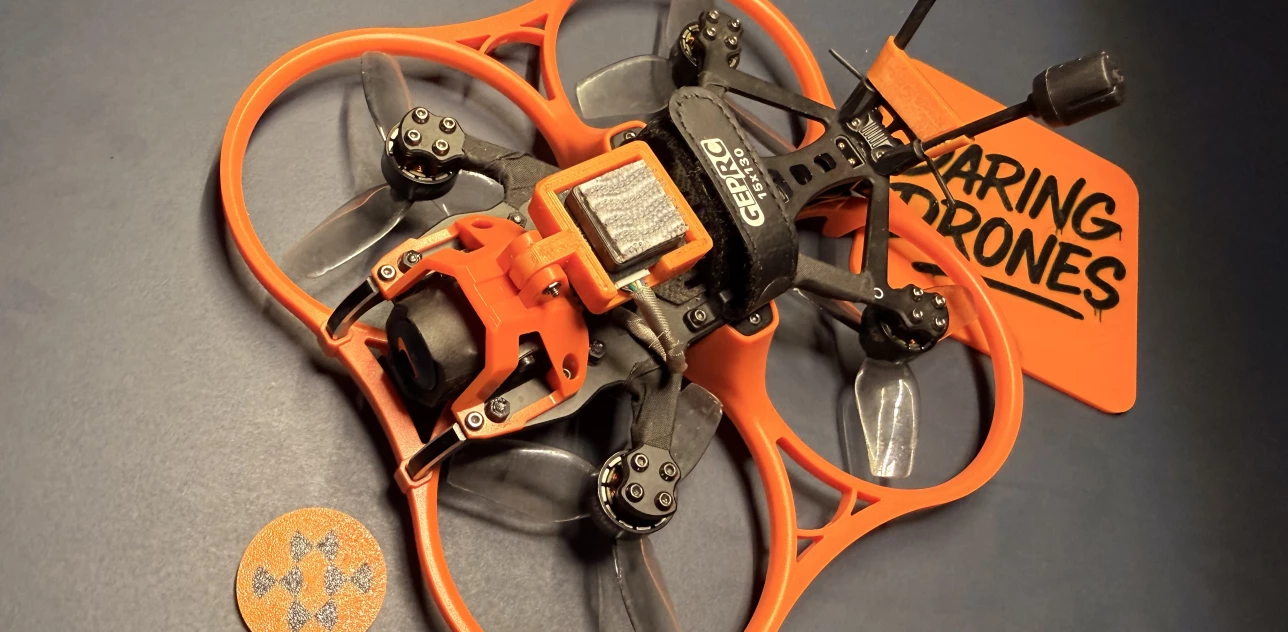
Building a Custom GEPRC Cinelog 30 v3 Cinematic Drone
This blog post provides a detailed account of the assembly process for a custom FPV drone designed for cinematography, indoor fly-throughs, and medium-range flights. The build integrates a SpeedyBee F405 AIO flight controller, DJI O4 Pro video transmission system, and ExpressLRS control link. The guide assumes familiarity with soldering practices, Betaflight configuration, and FPV system integration.
Bill of Materials
Frame
GEPRC Cinelog 30 v3
Electronics
Flight Controller: SpeedyBee F405 AIO
VTX: DJI O4 Pro
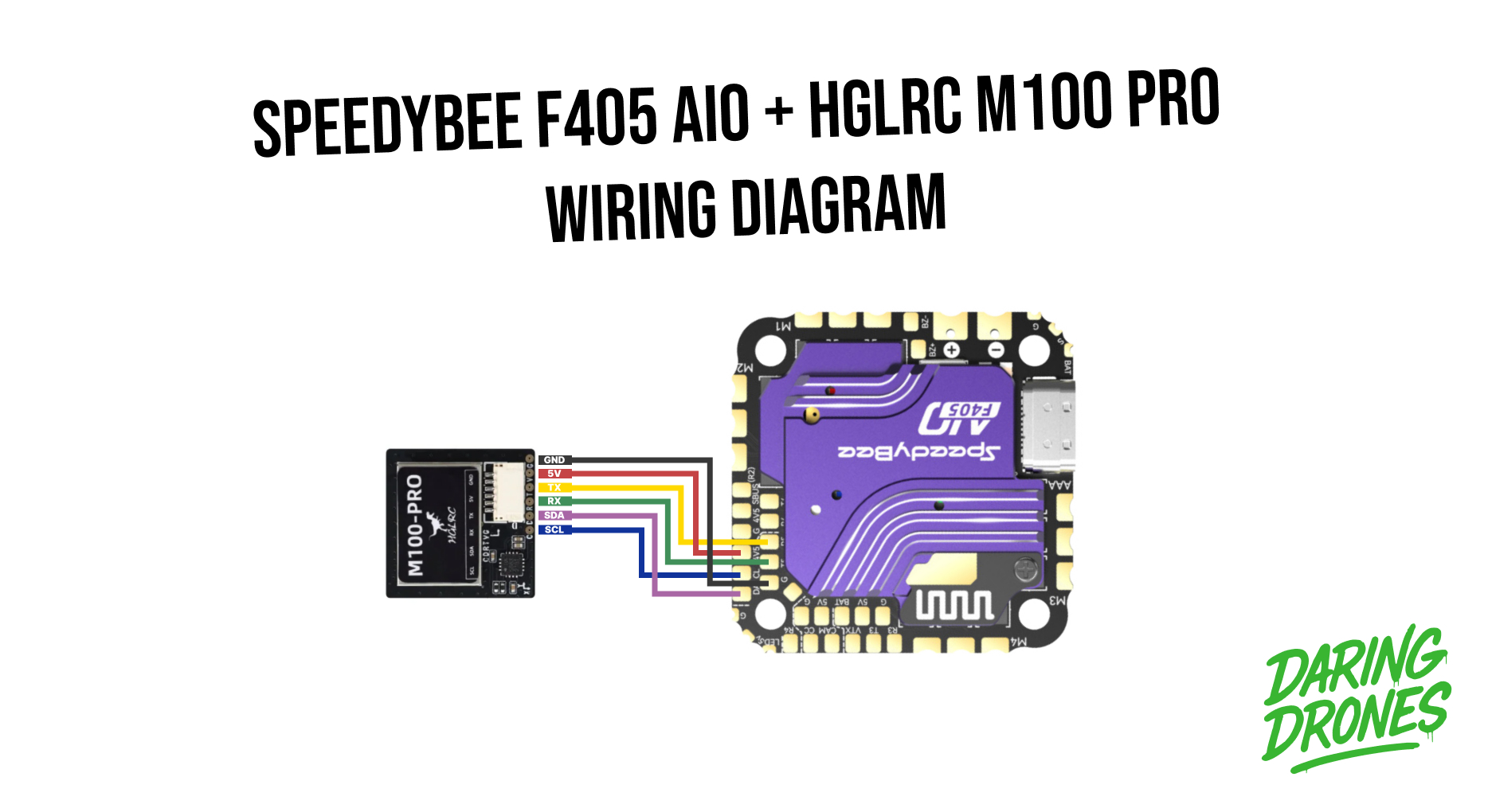
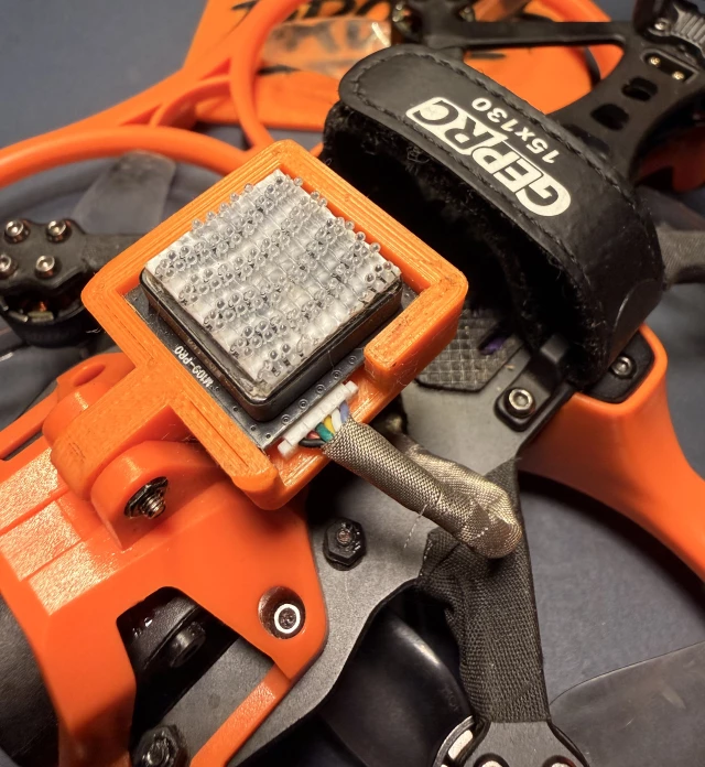
GPS: HGLRC M100-PRO
Receiver: GEPRC ELRS Nano 2.4G PA100
Camera and Air Unit: GEPRC O4 Air Unit Pro
Motors: GEPRC SPEEDX2 1404 3850KV
Capacitor: Supplied with FC
Propulsion
Props: HQProp DT76MMX3 V2
Power
XT30 LiPo batteries 4S 720 mAh and 850 mAh
Antenna System
HGLRC T antenna (AliExpress or Amazon)
Accessories
UV ND filters ND8 ND16 ND32 ND64
Wire harness tape
Heat shrink tubing
Battery slip pad and strap
Required Tools
Precision screwdriver set
Temperature-controlled soldering iron with fine tip
Leaded rosin-core solder
Flux paste
Tweezers
Wire strippers
Solder sucker and desoldering tool
USB-C cable
Smoke stopper (recommended)
Assembly Procedure
Step 1: Workspace Preparation
Lay out all components and tools. Verify completeness of the parts list before beginning. Clean the workspace and allocate uninterrupted time for assembly.
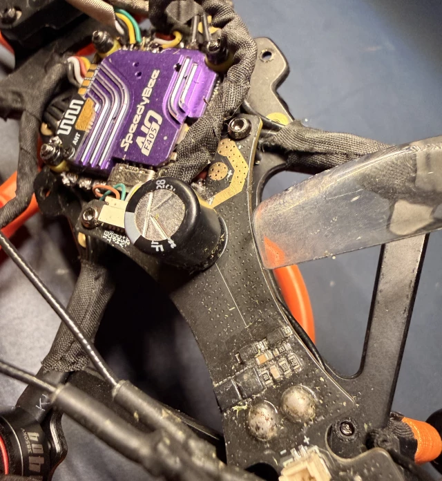
Step 2: Power Distribution Board and Capacitor
Set soldering iron temperature to high. Solder the XT30 connector to the breakout board. Attach short, thick battery wires to the board: red to positive, black to ground. Do not trim these wires short, as extra length is required due to the crisscrossed terminal layout on the SpeedyBee FC. Reduce iron temperature and solder the capacitor. The longer lead corresponds to positive and should align with the positive pad on the breakout board.
Step 3: Receiver Integration
Place a rubber support under the ELRS module to stabilize the overhanging board. Solder the ELRS receiver, observing correct pad orientation. Route and secure the antenna through the IPEX mount and the frame gap.
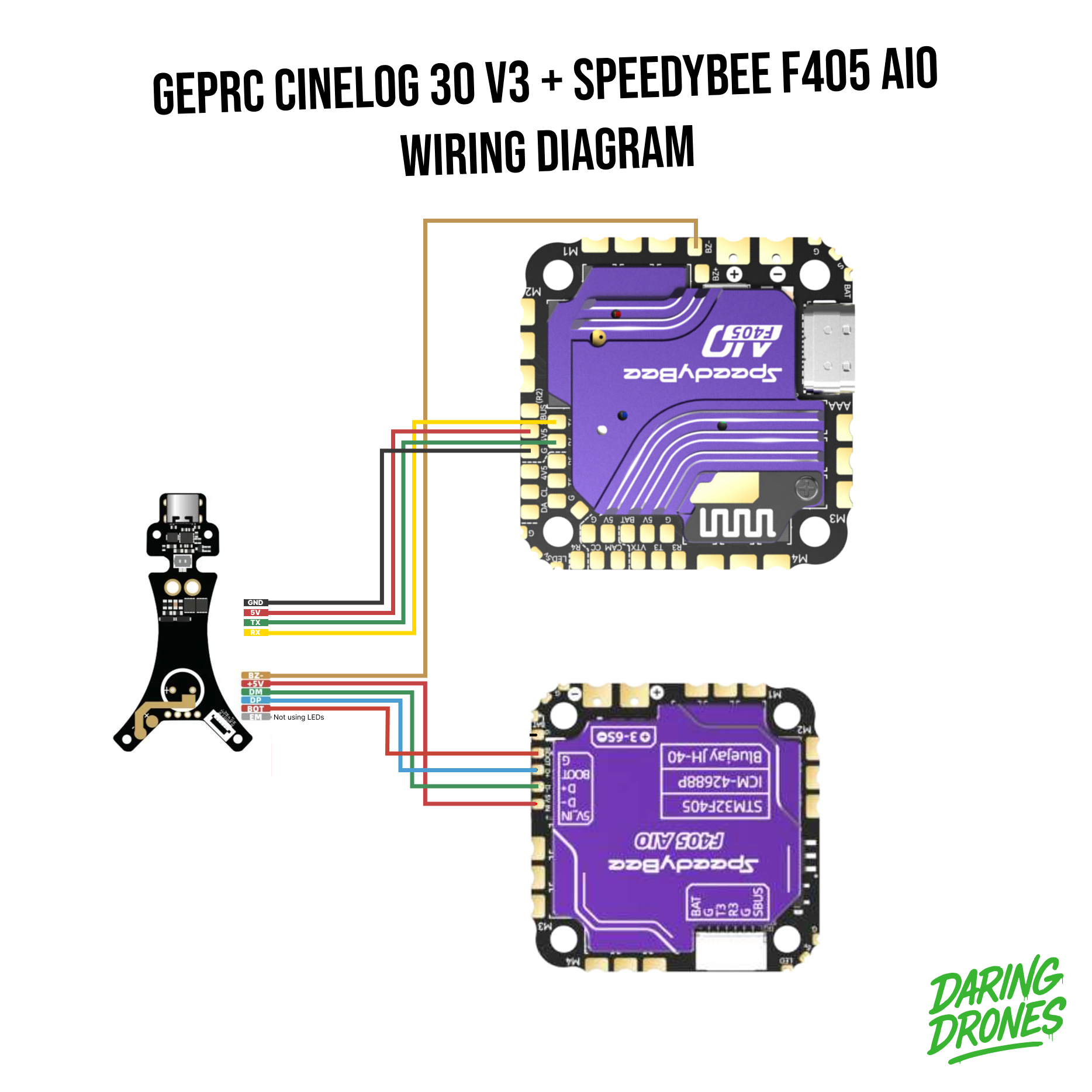
Step 4: USB Breakout and JST Connections
Solder the JST connector wires between the FC, breakout board, and ELRS receiver. Ensure RX is connected to TX and TX is connected to RX. Do not manipulate the wires after soldering as they are fragile. Leave the EM wire unused. Repeat the procedure for the GPS module.
⚠️ Be careful not to flick any solder onto any components on the FC, use a magnifying glass to check for stray solder balls. Though the Speedybee FC's purple heatsink protects most of the components, another benefit.
Step 5: Flight Controller and Breakout Board Mounting
Insert brass bushings into the carbon fiber frame. Mount the breakout board on standoffs. Use rubber grommets for soft mounting of the FC. Tighten screws only until snug to preserve vibration isolation. Connect JST connectors between the FC and breakout board.
Step 6: Motor Installation
Mount the GEPRC SPEEDX2 1404 motors to the frame. Trim motor leads to length, following arm geometry. Do not crisscross motor wires. Incorrect wiring will reverse motor direction but will not cause hardware damage. Solder wires directly to the FC at medium-high iron temperature.
Step 7: DJI O4 VTX and Camera Integration
Disassemble the DJI O4 VTX enclosure by removing four screws. Disconnect factory antennas and attach IPEX extension cables using heat shrink tubing. Do not disconnect extensions once installed to avoid connector damage. Mount the VTX onto the prop guard with four screws. Attach the camera to TPU mounts. Install grommets using the wire loop provided with the frame. Route antennas around the capacitor and standoffs into TPU holders. Tip: Wrap antenna bases with a single layer of harness tape for secure fit.
Step 8: Final Assembly
Arrange wires within the central frame cavity. Experiment with wire placement until the canopy fits without obstruction. Mount the 3D printed GPS holder and secure the GPS module. Install the battery pad and strap. Confirm that no wires interfere with propeller paths.
Step 9: Electrical Verification
Connect a smoke stopper in series with the power source. Insert a battery and verify correct power distribution. No smoke or overheating should occur. Connect the flight controller to Betaflight via USB-C and configure settings, you can start off with my CLI Dump here. This CLI backup has GPS Rescue enabled, crash_recovery on, 720 mAh battery capacity, OSD Layout, PID Tuning, cinematic rates, and expo on the throttle. You will probably want to configure your modes for your receiver.
Step 10: Flight Test
Attach propellers and perform an initial hover test in a controlled environment. Verify GPS lock (minimum 6 satellites), VTX video feed, and receiver link quality. Confirm correct motor rotation directions and failsafe behavior. Proceed to flight tuning once baseline functionality is established. Congratulations if you made it this far you kudos to you!
Conclusion
The completed GEPRC Cinelog 30 v3 build demonstrated excellent performance for cinematic FPV operations. Despite initial component setbacks with the Flywoo FC, the SpeedyBee replacement proved advantageous. Following the outlined procedure ensures a reliable and serviceable drone suitable for both indoor and medium-range outdoor cinematography.
Available in the Shop
We sell several accessories used in this build:
Related Blog Posts
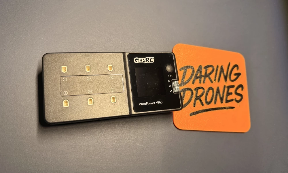
GEPRC Woopower W63 Firmware Update
Having issues discharging batteries that are full? Well there is a firmware update that fixes that.

DJI O4 Air Lens Mod
The DJI O4 Air lens mod significantly enhances the camera's narrow field of view, making it more suitable for cinematic and proximity flying. Several options are available, each with its own advantages.